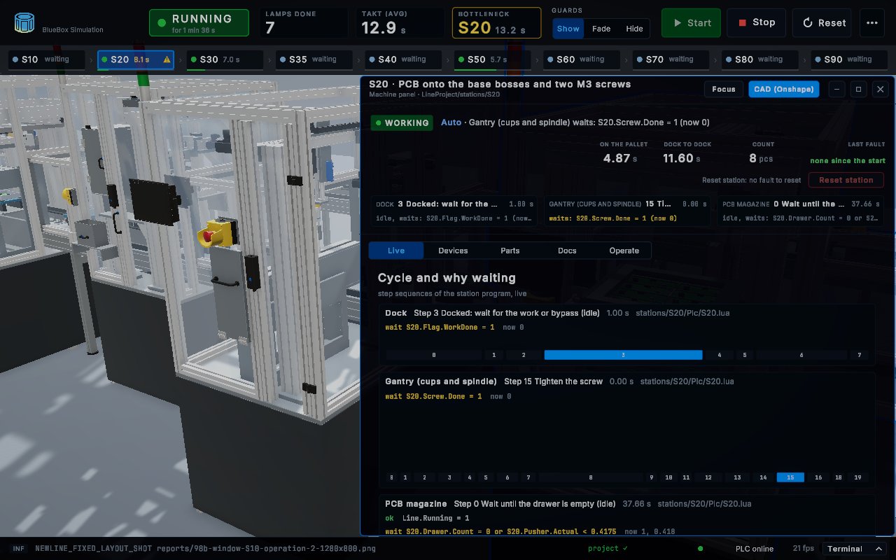
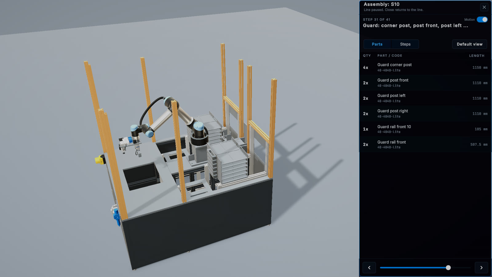
In a concept, an axis is defined by its stroke and speed. In the design it becomes a specific actuator with a catalog number, a mass, permissible loads and a physical envelope that has to fit among the other components. This is the stage where many assumptions are tested against reality, and where some of them change.
Scope of the stage
| Deliverable | Content |
|---|---|
| CAD of stations and line | Parametric model, drawings |
| Parts list | Components with manufacturer codes |
| Cut list | Profile and plate lengths and quantities |
| Assembly instructions | Station by station, written alongside the design |
| PLC and robot programs | Tested on the model |
| Signal list | Names, types and I/O addresses from the model |
| Electrical schematics | Prepared by our partners |
| Model of the line | For testing, training and acceptance |
We remain responsible to the customer for our partners’ work. Help with loading programs on site is an optional item, and it can be omitted if the plant or integrator has its own specialists.
Station architecture
Stations are designed the way automation manufacturers build them. A rigid machine table carries a milled base plate with a grid of threads and dowel holes, so that all modules and the transport dock share one reference system. Compact modules are chosen for the actual masses involved, ready-made manufacturer assemblies come first, and the minimum number of axes is used. The guard is a separate, light structure that carries no process forces.
Parts of the same function use the same model in every station, with only the parameters differing. For the plant this means fewer types of spare parts and fewer procedures to learn.
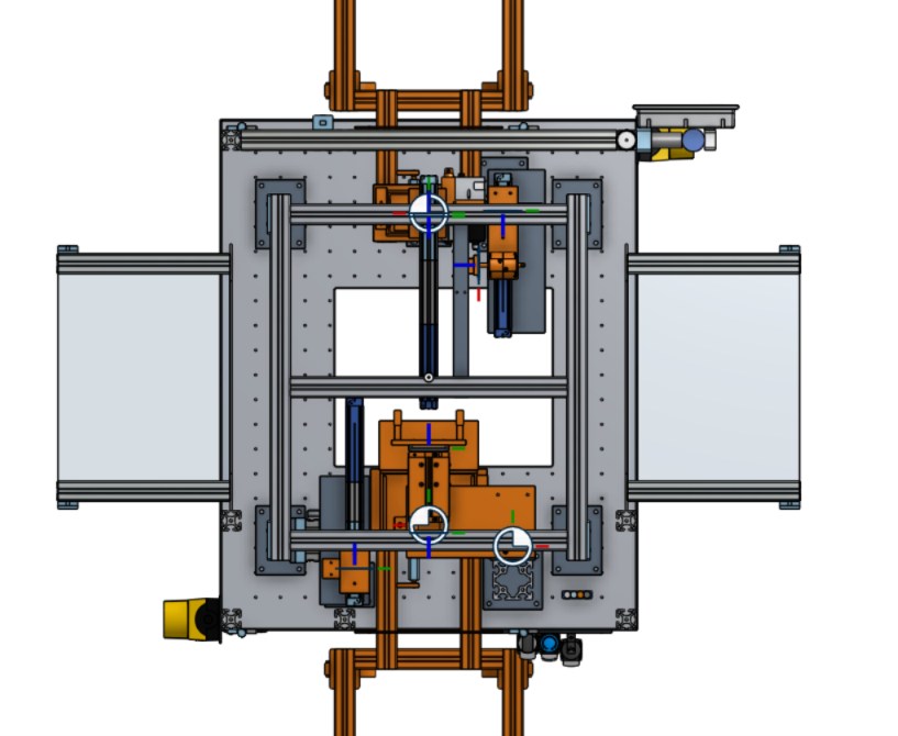
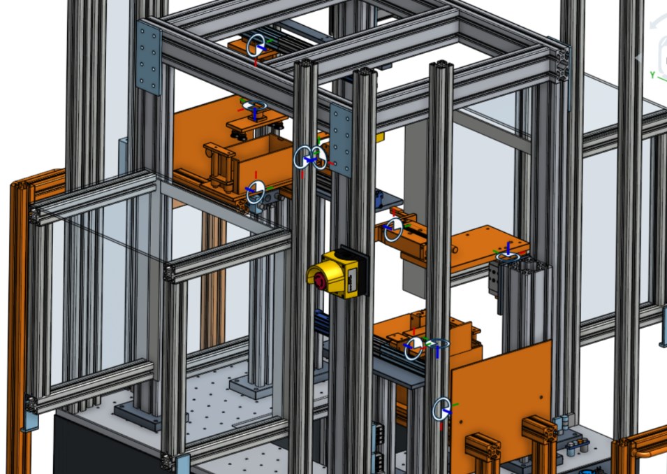
A station in Onshape. The markers are the connectors that join parts in the assembly, matching the real guides and rotations.
How a review changes the design
Station S35 shows how this works in practice. The first version had a 1200 × 1300 × 1900 mm cage of 40-4080 profiles and a manipulator with 500 and 300 mm strokes (Festo EGC-70-500 and EGSL-75-300). After the design review the station stands on a table with an 800 × 860 mm base plate, and the head pick-up nest moved close to the dock. The horizontal stroke dropped from 478 to 178 mm, and the estimated moving mass of the horizontal axis from about 8 to 4.2 kg.
The same review simplified the screwing. A DEPRAG SFM-L module with a 25 mm stroke on a short Festo EGSC-45-100 axis replaced the EGSL-75-300 axis with its DFM-16-50 actuator, and the force loop of the screwing now closes within one column.
Automatic checks in CAD
Before a station is reviewed by an engineer, it passes an automatic check of the CAD model. The check looks for parts that intersect, near-contact, parts with no support, missing fasteners, parts with no defined role, and insufficient clearance along the whole travel of each axis. It also checks that nothing fixed stands in the way of a door opening.
For S35 the check covered 227 bodies, including 34 moving ones, and returned no findings. Clearance is reported for each axis:
| Axis | Range, mm | Smallest clearance, mm | Location |
|---|---|---|---|
| ManipY (ELGC-60-200) | 0–178 | 19.0 | Tool plate – parked spindle nosepiece |
| ManipZ (EGSC-45-150) | 0–134 | 12.0 | Presser pad – nest strip |
| Pusher (DGC-K-18-200) | 0–190 | 11.0 | Latch – tower gate |
| SpindleY (EGSC-45-100) | 0–92 | 12.0 | Module carrier – arm |
| SpindleFeed (SFM-L) | 0–25 | 21.5 | Spindle holder – ELGC |
These conditions are written into the design rules from the start. The check at the end only confirms them, so problems are avoided instead of being found later.
Load and stiffness
Axis loads are compared with catalog limit values. The load comparison factor must stay at or below 1.
| Axis | Moving load | Factor |
|---|---|---|
| SpindleY EGSC-45-100 | 2.9 kg | 0.79 in motion, 0.25 when screwing |
| ManipY ELGC-60-200 | 4.2 kg | 0.41 at the 120 N force limit |
| ManipZ EGSC-45-150 | 1.8 kg | 0.36 for moments, 0.52 for feed at 80 N |
| Pusher DGC-K-18-200 | 0.65 kg | 0.2 for force |
The force path of the process is also traced. For the snap fit, it runs from the presser pad through the force sensor, the axes and the portal beam to the base plate, and back through the conveyor and pallet to the part. At 120 N the tool moves by about 0.1 mm, which is negligible in the force-displacement record over the 4 mm snap travel. Some inputs, such as the mass of the screwing module, are estimates at this point and are confirmed with the manufacturer’s sizing tools when ordering. The verification report states which values these are.
Safety in the design
Safety requirements are included as design rules: guard height and opening distances according to ISO 13857, interlocks with guard locking according to ISO 14119, emergency stops on each station, behavior of vertical axes after loss of power and air, and refilling magazines from outside the guard. A model helps to check such a design, but it does not replace the risk assessment, nor the validation of safety functions on the physical equipment.
Programs and signals
Programs are written against the model, and the signal list comes from it. The lamp process has about 470 inputs and 140 outputs across ten stations. Each signal has a name, a type and a description before it reaches an electrician, which gives a concrete basis for designing the control cabinet.
From design to assembly
The model, the parts list and the cut list produced in this stage are also the source material for the assembly instructions. The stage ends with everything needed for the handover of the model to the implementation team.