Assembly instructions are often the last document in a project. They are written when the machine already exists, by someone working backwards from the finished result. By then, there may be differences between the design and what was built, and knowledge about the sequence sits with a small number of people.
Here, the instructions come from the same model as the design. They work like the pages of a building-block manual: each group of parts has its own step, and the model grows from the base to the finished station.
What a step looks like
The instructions are part of our software, and they use the three-dimensional model instead of static drawings.
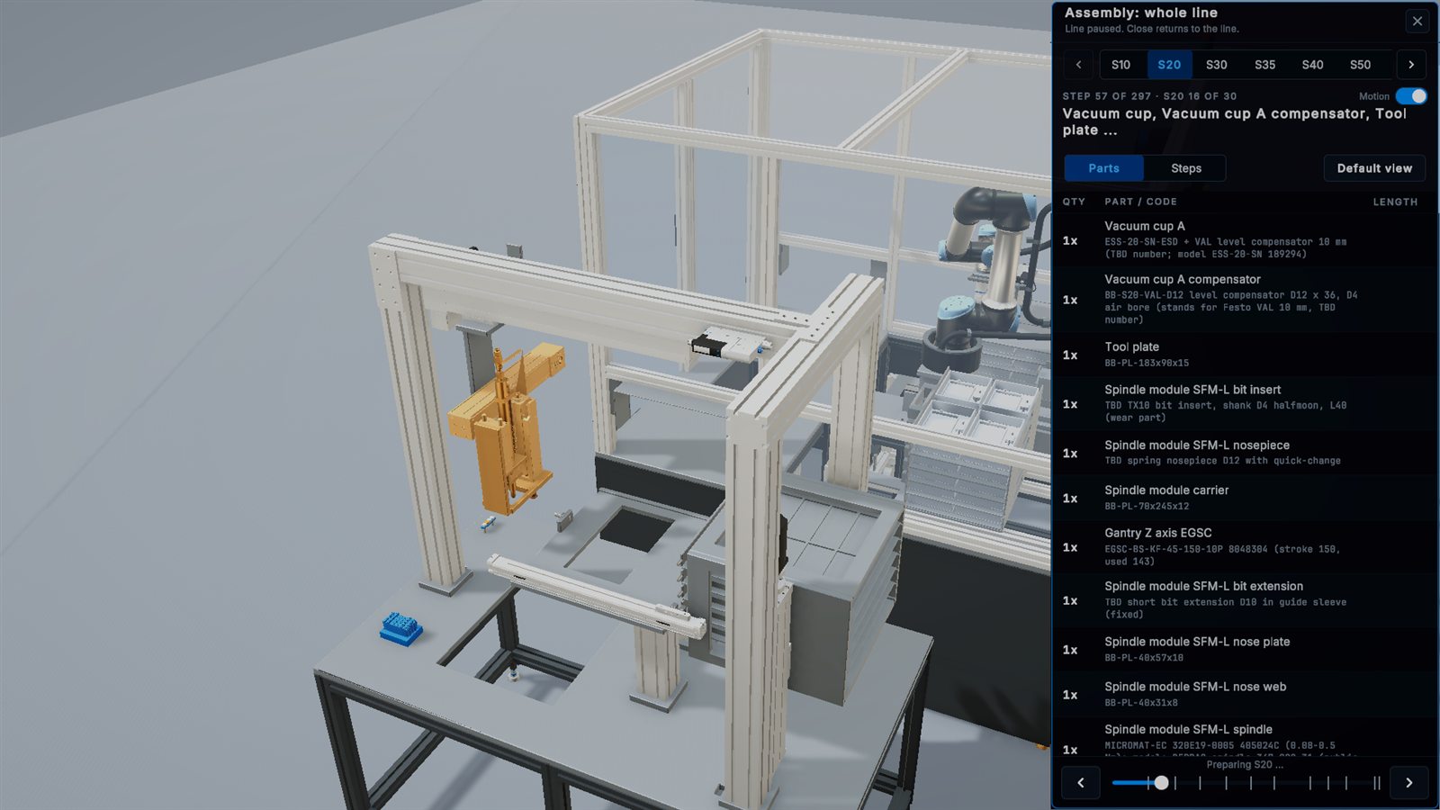
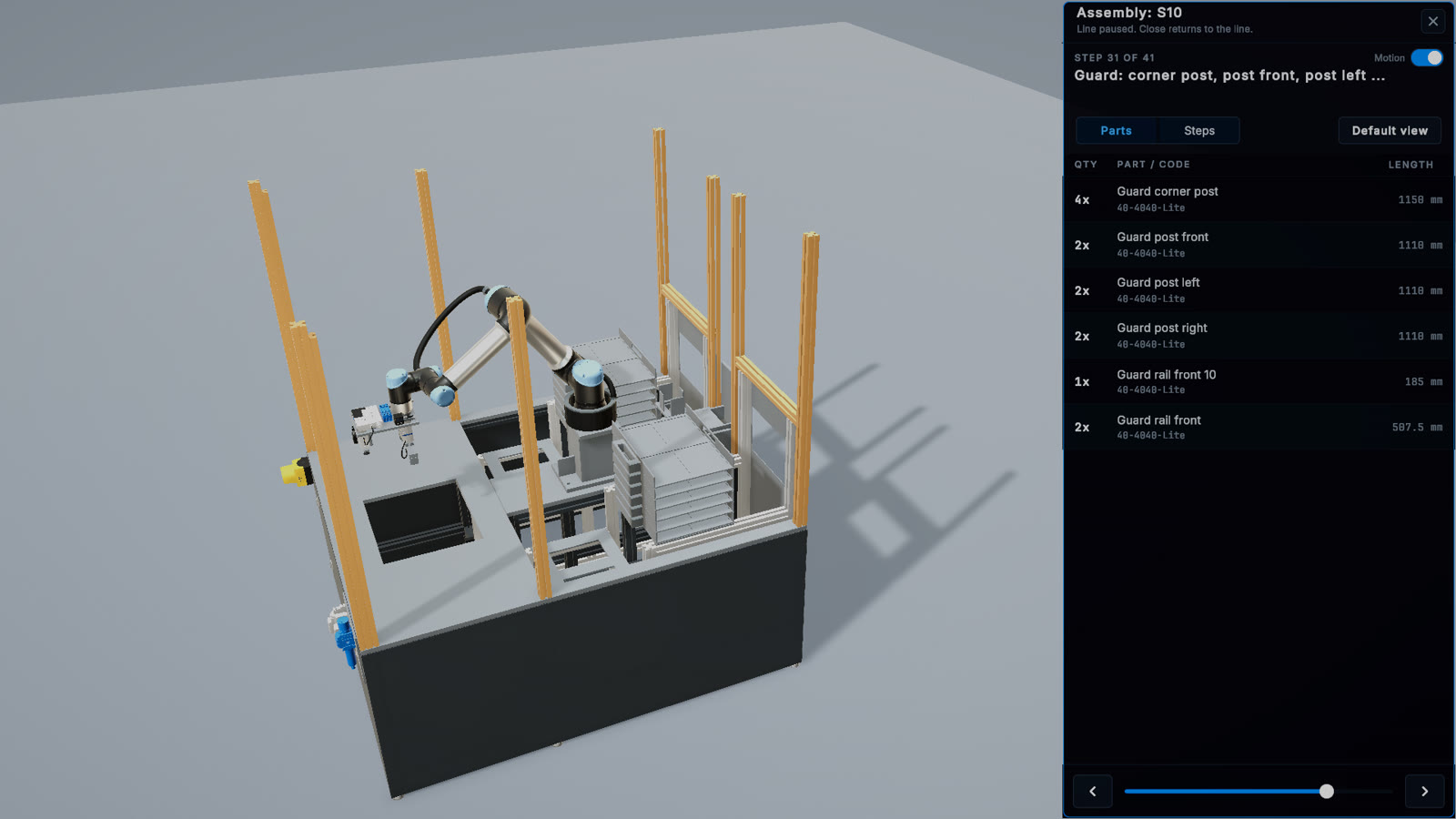
- The 3D model shows all parts fitted up to that step. New parts are highlighted in color and can be viewed from any side.
- The parts list gives the quantity, name, catalog code and profile length.
- Navigation: arrows, a scroll bar and a list of all steps. The step number is always visible.
- Assembly motion: an optional animation shows where a new group of parts comes in from.
How the order is determined
The order comes from a generator, not from manual description. Using the position of the parts, it builds a support graph and works from the floor upward. Parts are grouped into steps by assembly, with at most 16 per step, and guards come last in each station.
An automatic test checks that every part of a station appears in the instructions exactly once, and not before whatever supports it. Exceptions are listed explicitly in the file. There are 73 across the whole line, and the most common is the guard tunnel bracket, which stands on a transport section.
The result is stored in a readable file for each station. It can be edited by hand, and notes entered by an assembler or designer survive when the instructions are regenerated.
Scale on the LED lamp process
| Section | Steps |
|---|---|
| S10 | 41 |
| S20 | 30 |
| S30 | 27 |
| S35 | 29 |
| S40 | 28 |
| S50 | 25 |
| S60 | 40 |
| S70 | 20 |
| S80 | 20 |
| S90 | 31 |
| Transport and line connection | 6 |
| Total | 297 |
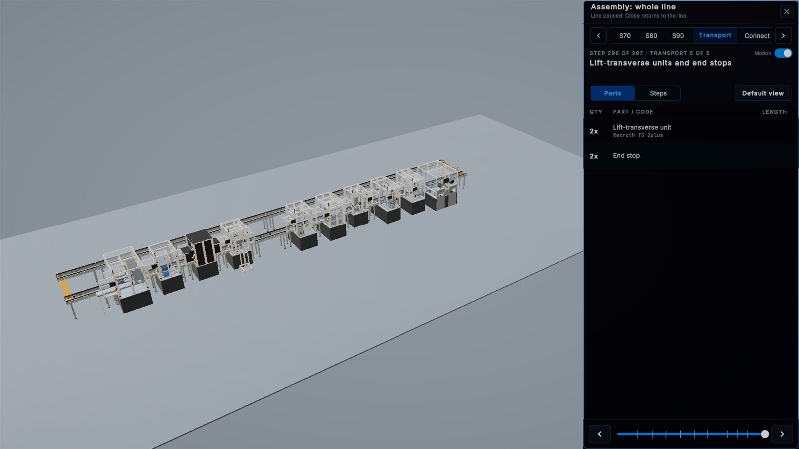
The whole line uses the same window. You can go to any station or step through in order, and the scroll bar covers the entire line.
Cut list
The cut list comes directly from the CAD model in Onshape.
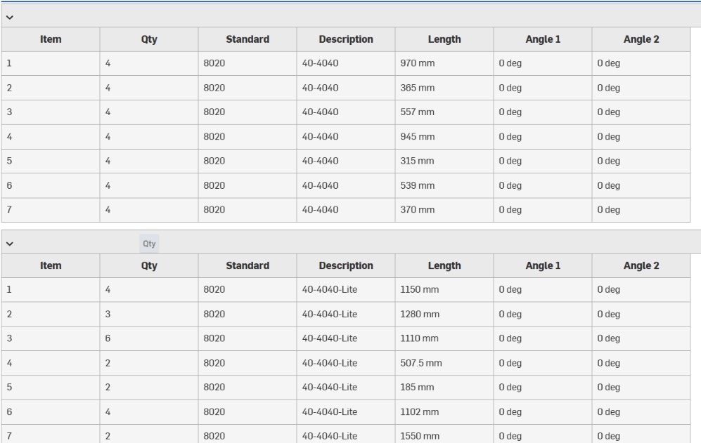
Each row states which profile to cut, to what length, at what angle and how many pieces. Material can be prepared and packed per station before the assembly crew starts work.
Parts list
The parts list from the same model contains manufacturer codes and our own part numbers.
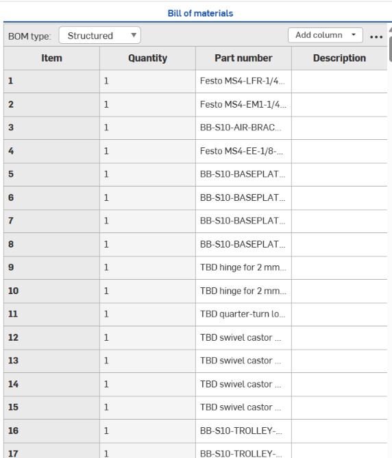
Items awaiting confirmation with the manufacturer are marked directly, so it is clear what must be closed before ordering.
The whole line, step by step
What the instructions do not yet contain
The model does not know everything needed on site, so these gaps are named directly.
- Tightening torques are not in the data of the lamp process. The instructions have a field for them and show a value only when one has been given. We do not insert numbers that nobody has specified.
- Connections between stations: the line data gives the transport sections, docks, separators and pallets. It does not give floor anchoring, section connectors, air, power and network, which a note in the last step describes.
The instructions are also not part of the public demo, only of the software handed over in a project.
Scope and formal requirements
The instructions cover the mechanical structure of the stations. They do not cover commissioning the line on site, and they do not replace the operating and maintenance manuals.
A station supplied without the complete safety equipment of the line is usually treated as partly completed machinery, supplied with a declaration of incorporation and assembly instructions. Regulation (EU) 2023/1230, applicable from 20 January 2027, also allows this documentation in digital form, under conditions. The instructions described here are a technical input to that documentation, not a substitute for a compliance assessment.
What this gives the project
- Assembly can be priced earlier. A contractor quotes on a concrete list of steps and parts.
- Material logistics can be planned. Cut lists and parts lists can be prepared per station and per step.
- The knowledge stays documented. The sequence does not depend on the memory of the person who designed the station.
- It stays current. After a design change, the instructions can be regenerated instead of being rewritten by hand.