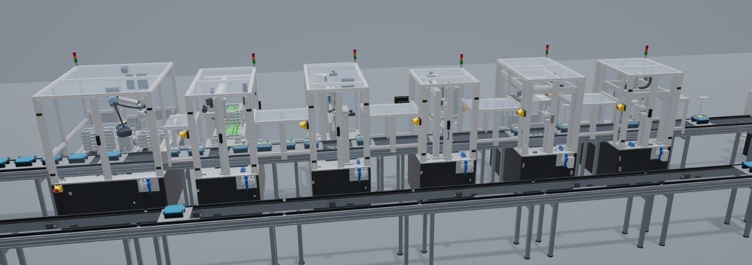
BlueBoxSimulation builds a digital representation of the machine. This gives AI an accurate view of how each machine behaves: its sequences, signals, cycle times and reactions to faults. It is a way to hand over the complete context and take the largest possible number of variables into account, instead of describing a machine in a few sentences.
A language model also receives an environment on which it can iterate and see the effects of its work. It makes a change, the model executes it, and the result returns as signals, cycle times, collisions and faults. A wrong proposal ends as a result in simulation, not as a stopped line.
The same environment makes it possible to train own lightweight models. Data from simulation runs teaches them the behavior of a specific line, for example to predict output or detect deviations, with no need to wait for data from the floor.
Why AI needs this context
AI models have limited value on the factory floor for a simple reason: they have nothing to read. Controller tags have cryptic names, drawings are stored as PDFs, the sequence is contained in a program and the reasons for it are in the heads of the people who wrote it. Connecting more data does not solve this by itself. A stream of values without meaning is still only a stream of values.
The model can act as a window onto production for AI.
What building a model requires
For a line to run in simulation, it must be described precisely. This description is a by-product of the work, and it happens to be what analytical software needs.
| Element of the model | What it provides |
|---|---|
| Stations and their order | The flow of the product through the process |
| Named signals with a description | The purpose of each input and output |
| Axes with ranges and limits | The permitted states of the equipment |
| Parts with process history | What was done to a given product, and where |
| Expected cycle times | How long each step should take |
| Parts list | The real component behind each function |
| Rules and checks | What counts as a fault |
A concrete example is the signal S35.Screw.Ok. In the description of the station it means that the DEPRAG controller has reported torque and angle within the window, and the torque window is 0.35–0.45 Nm. A controller address alone gives none of that. With this description, a question like “why are screws being rejected at S35” has a starting point.
The line as project files
On the lamp process, this data is not locked inside an application. The line is described in project files: one file for the line, a package per station with its requirements, concept, parts list, signal list and verification report, and one program per station. They are readable text and structured data, so software can read them without opening a 3D view.
Each run of the model also records production metrics, and line variants, such as transport speed, pallet count, defect rate or station speed, are described in files. Variants can be run one after another and compared side by side.
What this could enable
Four applications follow from this structure.
- Questions about the line in natural language. “Why did S35 stop?”, with an answer based on actual signals and the sequence.
- Detecting deviations. Comparing how the line runs with the expected behavior, and pointing to where it starts to differ.
- Finding constraints. Identifying the station that limits output and explaining why, on the basis of measured cycles.
- Exploring design variants. Design rules and a catalog of modules keep the set of variants finite, and each variant can be checked automatically for cycle time, collisions and cost.
The boundary: read-only
Near production, safety comes before convenience. A connection between the model and a running line would be read-only: the model reflects what the line is doing, and the controller remains in charge of interlocks. A start or stop issued from the model could only be a request that the PLC decides on. AI does not issue commands to machines, and interlocks are never bypassed.
Regulation is moving in the same direction. Regulation (EU) 2023/1230 includes requirements on protection against corruption of safety functions, including through network connections, which is another reason to keep this boundary strict.
What can be prepared now
A customer planning a line can already make decisions that keep this path open: consistent signal naming from the start, a signal list with descriptions, and sensors at the points where later analysis will need them. These decisions cost little during design and a great deal to change afterward.
The most concrete application of this foundation is maintenance: predicting failures before they stop the line.