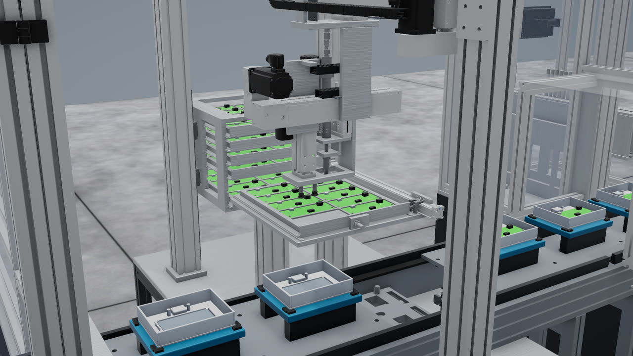
The concept stage carries the highest leverage in a project. The decisions made here, such as the division into operations, the number of stations and the feeding method, determine most of the later cost. They are also the cheapest to change, since nothing has yet been ordered or built.
Input data
The work begins with the product and the production target: the part and its components, the required output, available staffing and floor space. Not all of this needs to be complete at the start. Missing data can be developed by us as part of the project.
All of it is recorded on an assumption card, which separates four categories:
- the target, meaning the output the process must reach;
- confirmed and estimated data, kept explicitly apart;
- constraints, such as space, budget, existing equipment or staffing;
- unknowns, along with how and when they will be resolved.
The card defines the scope of the work. At the end of the stage, the result is compared against it.
From requirements to stations
For each station we follow the same engineering sequence, in which every step is a checkpoint:
- Requirements: operations and their order, product dimensions and masses, takt, and the motions needed: what moves, from where to where, with what stroke, speed, force and accuracy.
- Kinematic concept: axes, grippers, magazines, a first selection of catalog components and a cycle time balance.
- Layout: views, motion zones, collision envelopes and main dimensions.
The governing rule is that the design follows from motion and handling needs. A station is not drawn first and then made to work. Ready-made manufacturer modules are preferred over custom ones, and the same components are reused across stations, which means fewer types of spare parts later.
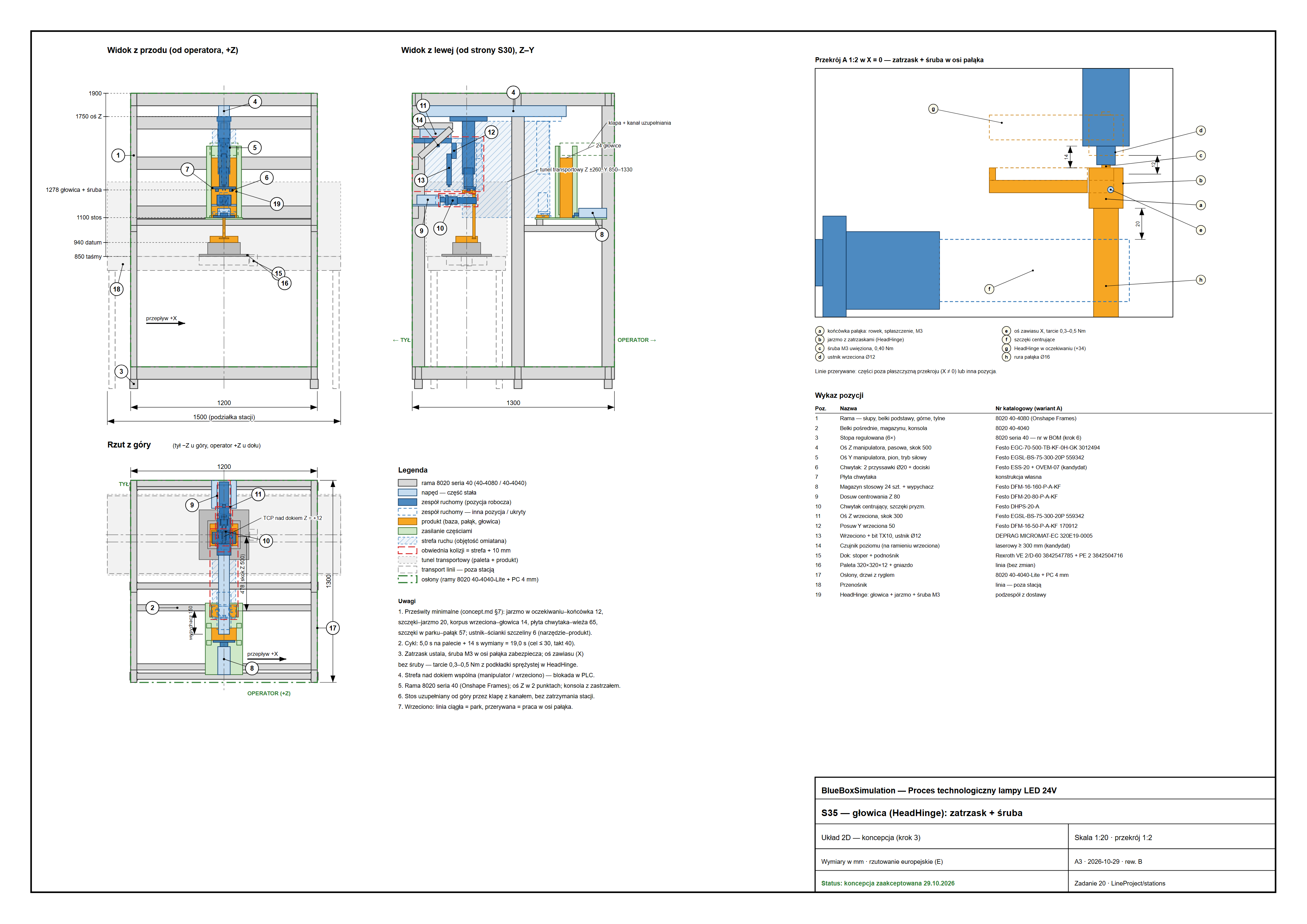
Example: station S35
Station S35 places the head on the lamp’s stem: a snap fit locates it and an M3 screw secures it. The requirement was a cycle of no more than 30 seconds, against a line takt of 40 seconds assumed in the concept.
The balance came out at 4.3 seconds of work on the pallet plus 14 seconds of pallet exchange, or 18.3 seconds in total. Because the next head is picked up away from the pallet, in parallel with the screwing and the exchange, the handling time does not add to the time on the pallet. This is the kind of decision that shows up clearly in a balance and is difficult to see on a drawing. Later reviews and the model shortened these times: in the working model, the mean takt of the whole line is now about 12.2 seconds.
The concept also records clearances between moving parts: for example, 19 mm between the tool plate and the screwdriver nosepiece, with the spindle parked and the manipulator over the dock. Those figures feed the design rules for the next stage.
From station balances to the model
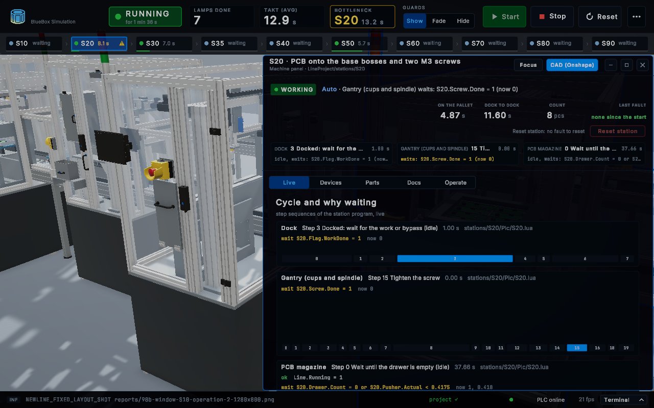
A balance on paper assumes that stations do not influence one another. A line does not behave this way: pallets queue, one station waits for another, and the longest cycle sets the pace of the rest. That is why the concept is built into a model in which the stations and transport run together under control logic.
The model shows the output reached by the whole process and identifies the station that limits it. Variants can then be compared on the same basis, such as moving an operation between stations or adding a parallel one, and each comparison gives a measurable result.
What the stage delivers
- the process, divided into operations and stations;
- the layout and equipment concept of each station;
- a working model of the process;
- the achieved output and the identification of bottlenecks;
- a list of decisions to approve, each with the options, their consequences and a recommendation.
What counts as a result
The acceptance criterion is that the model shows the process making the given part at the assumed output. If the assumptions cannot be met within the agreed constraints, a properly demonstrated best result is also an accepted result. A concept that shows, before the investment, that a target is unreachable has fulfilled its purpose.
Limits of this stage
The concept is built on first selections of components, and masses and interfaces are refined in stage 2. Its output figures therefore hold for the assumptions listed on the card.
After approval
An approved concept fixes the process, the stations and the target output. The next stage replaces assumed equipment with specific components, and the concept’s cycle balance becomes a requirement that the design must meet.