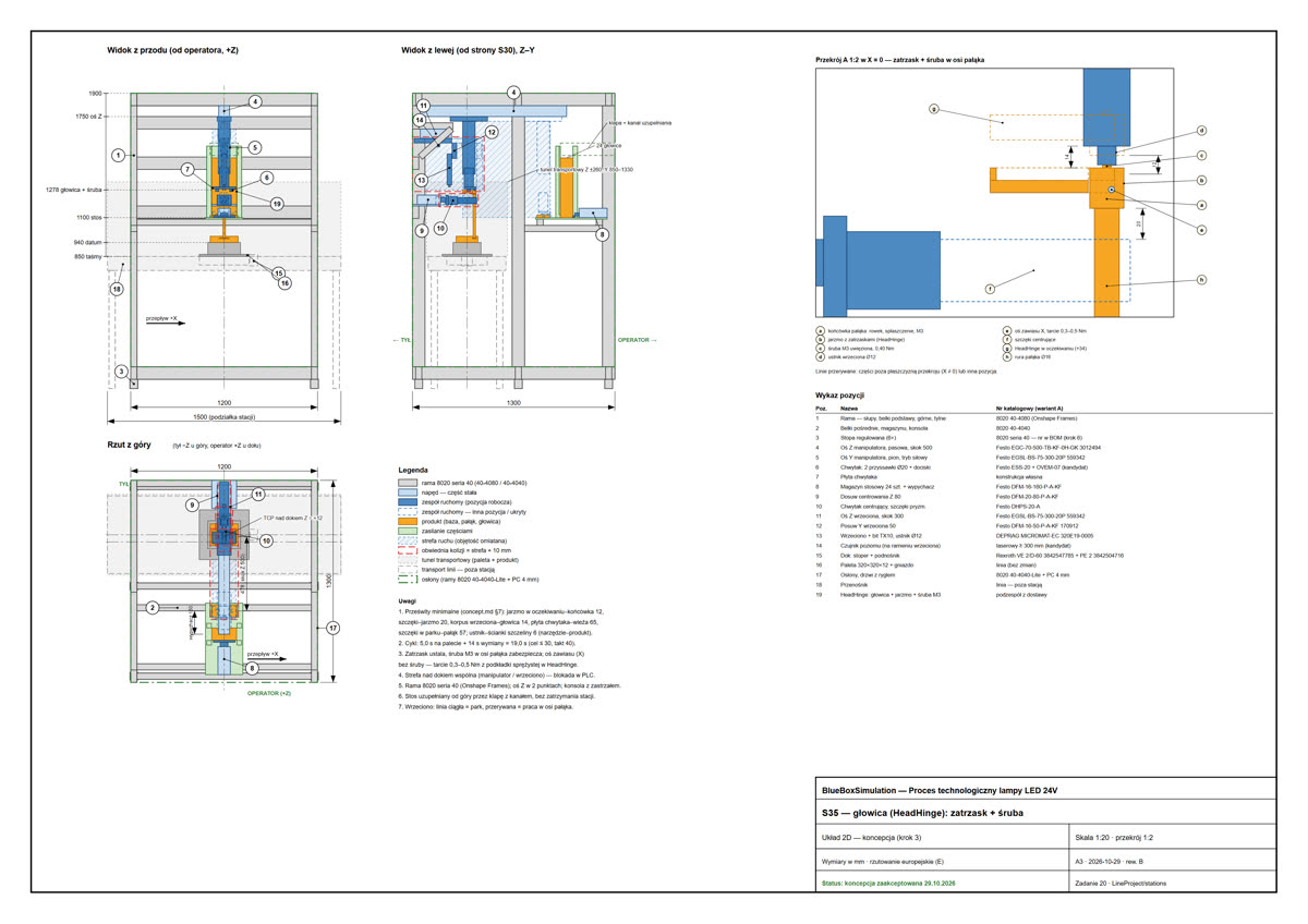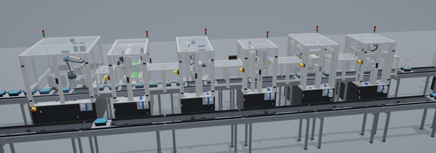
To verify this way of working on a real product, we designed an entire process: automated assembly of a 24V LED lamp, from an empty pallet to a tested and labeled product in a tray. A real product imposes real decisions: part dimensions, joining methods, test procedures and the feeding of components.
The process, station by station
| Station | Operation |
|---|---|
| S10 | UR5e robot places the lamp base and ballast in the pallet nest |
| S20 | PCB placed on the base bosses, fastened with two M3 screws |
| S30 | Stem inserted and fastened with two screws |
| S35 | Head placed on the stem: a snap fit locates it and a screw secures it |
| S40 | Thermal pad and LED board placed in the head |
| S50 | LED board fastened with two M3 screws |
| S60 | Diffuser and base cover fitted, head turned by 180° |
| S70 | Functional test: 24 V supply, current, light |
| S80 | Serial number label applied, final read |
| S90 | Unloading to trays: a lane for good lamps and a lane for rejects |
Example: station S60
S60 fits the diffuser and the base cover, then turns the lamp head by 180°. In its first version it was the bottleneck of the process, at about 75 s per lamp. Three tasks ran one after another, and the tools traveled 0.5 to 0.85 m for each part.
The tasks do not depend on each other apart from the head support, so each one got its own short actuators next to its magazine:
- Diffuser: a slide with four suction cups waits over the stack and picks a part when a lamp for this station is on the stop.
- Cover: a latch on a carriage slides the top cover from the stack onto the base, and an actuator on the same carriage presses it down by 12 mm.
- Head rotation: a cradle with a rotary actuator grips the end of the head and turns it by 180° around the hinge.
The design balance gives about 4.6 s on the pallet and 10.6 s with a six-second pallet exchange, so S60 is no longer the bottleneck. Diffusers and covers stand on two trolleys of 30 pieces each. Both are exchanged whole from outside the guard every 30 lamps, without entering the station.
Key figures
| Parameter | Value |
|---|---|
| Stations | 10 |
| Transport | Pallets on a conveyor with a return lane, 29 pallets in the model |
| Signals | About 470 inputs and 140 outputs |
| Mean takt measured in the model | About 12.2 s (test run of 72 lamps) |
| Time to build the process and model | About 10 days |
The time of about ten days covers the process, the stations, the robot, the control logic and the model. It is a single measured project. The schedule of another project depends on its data, decisions and review rounds.
Control logic
Each station has its own program, written as a module of a software PLC that scans inside the simulation. A separate program coordinates the line. Each program sees the plant only through its process image, so a real controller can take its place through the same signals. A changed program takes effect at the next reset.
A fault in a station’s program stops only that station, while the other programs continue. The behavior on a restart is defined as well: axes return home by moving there, in a safe order, and the station determines its state from its inputs.
Product tracking and defects
Each lamp is identified by a serial number and carries a history of the stations that have worked on it. Finite stock really runs out: if a magazine is empty, the station requests a refill and waits. A station does not start work on a lamp unless the previous station has recorded its work as complete.
Defects enter the process at their source, as they would in a real plant. An LED board with a shorted string is fitted at S40, or a driver with an open circuit at S20, by default in 5% of lamps. The lamp continues until the functional test at S70 finds the defect. It is then marked as rejected, skips labeling at S80 and is placed on the reject lane at S90.
Documents for each station
The process is described in project files. Each station has its own package, and the documents correspond to those described in the previous articles:
- requirements, with the operations, motions and takt;
- a kinematic concept, with the component selection and cycle balance;
- a layout with motion zones and collision envelopes;
- a parts list and a cut list;
- a verification report covering clearances, loads, force paths and stiffness;
- a signal list and a program.
See it running
The button at the top of this page opens a virtual walkthrough of the running line. After entering a work email, the process runs in the browser with nothing to install: you can move along the line, view each station up close, click it and see its current step and signals. It is best viewed on a computer.