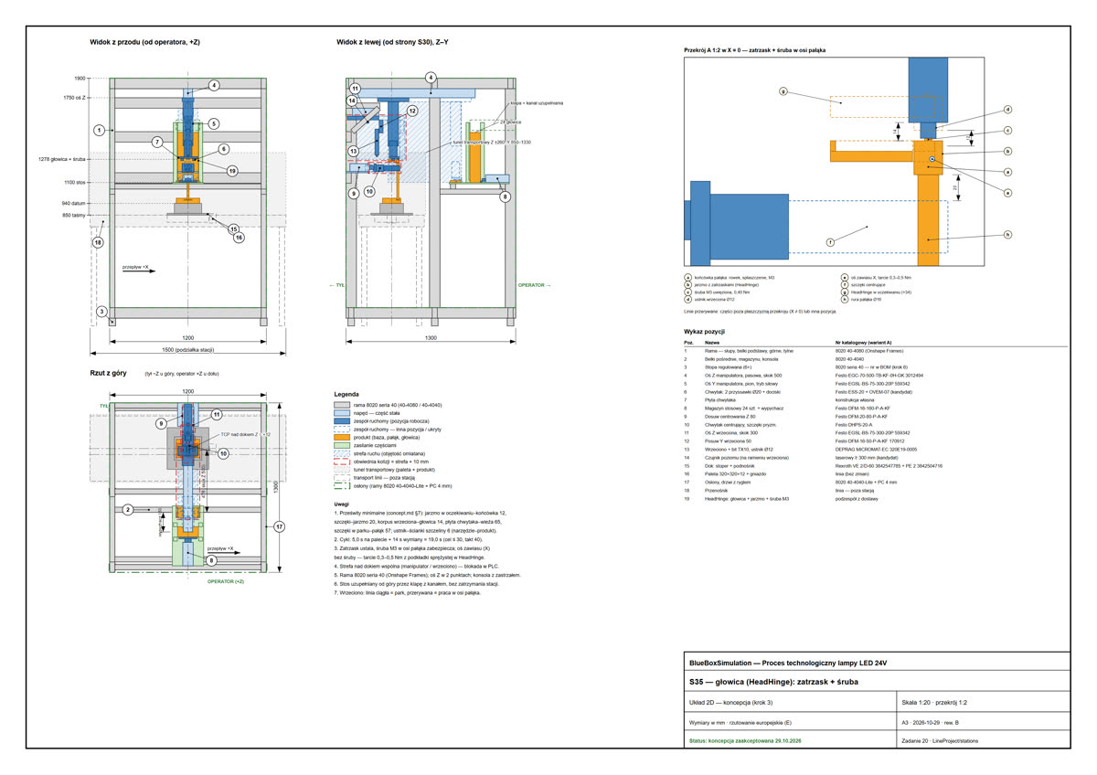
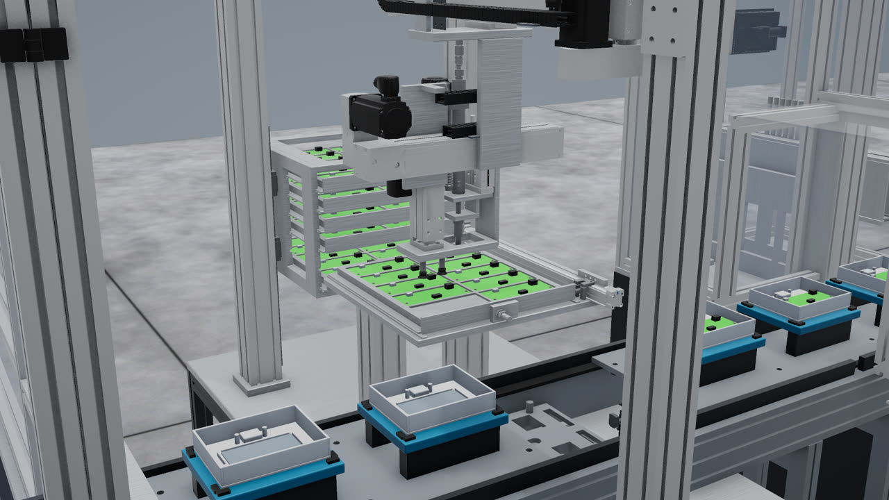
Most production lines are specified with CAD models, layout drawings and process charts. These documents describe the intended result well, but they cannot show how the elements behave together. PLC logic, robot paths and mechanics usually meet for the first time during commissioning, when correcting an error is most expensive.
Our method moves that first meeting to the beginning of the project. The process is built as a working model with control logic, and the model remains the reference point for every later decision.
Scope of the project
We are responsible for the concept and design phases: from the first assumptions to a design ready to implement. That covers the stations, component selection and the PLC and robot programs, tested on a model based on a real control system. We do not assemble lines ourselves. Assembly is carried out by the customer’s integrator or by our assembly partners, under a contract with us and with our supervision against the design.
Stage 1: concept
The first stage answers whether the process can reach the required output under the agreed constraints. It produces the process, the stations, a working model and the achieved output. The stage can be ordered on its own, and it has a complete result: the investor receives a verified basis for the decision, regardless of what happens next.
Stage 2: design on real components
After the concept is approved, assumed equipment is replaced with catalog components. This stage produces the CAD with drawings, parts list, cut list, assembly instructions, tested programs, signal list and electrical schematics. Our partners prepare the schematics, and we answer to the customer for the result.
Stage 3: model handover
The model is handed over as our own software, for the people working on the implementation. Each person can check how the result should look and behave, which gives the whole team one reference.
How the work is organized
| Step | Result |
|---|---|
| Conversation and review of materials | Agreed initial scope |
| Offer with an assumption card | Target, confirmed and estimated data, constraints, unknowns |
| Order | Start of work |
| Handover of materials | CAD, recordings, data, access to the controller, depending on scope |
| First version for review | Link or installer |
| Up to two rounds of comments | Agreed corrections |
| Acceptance and handover | Final version and documents |
Changes outside the agreed scope are agreed before they are carried out, with their effect on the schedule stated. Errors on our side are corrected, and for 30 days after acceptance we correct anything that does not work as agreed.
Acceptance criteria
The model must show that the process makes the given part at the assumed output. If the assumptions cannot be met within the agreed constraints, a properly demonstrated best result is also an accepted result. For example, a demonstrated 20,000 parts a month against a target of 22,000 is valuable information obtained before the investment, not a failed project.
What “plug and play” means here
We use this term in a specific sense. In the traditional approach, the program meets the machine on site. In ours, the program has already run through every station of a working model of the same process, on a model based on a real control system. When the line arrives, the logic has already been tested. Contractually, we commit to programs tested on that model. Corrections after physical commissioning, if required, are a separate, optional item.
Rights and confidentiality
The framework and the source project of the simulation remain with BlueBoxSimulation. A non-disclosure agreement is standard.
How far the method has been measured
Our reference is a 24V LED lamp assembly process: ten stations, a robot, control logic and a running model, built in about ten days. This is one measured project. The schedule of another project depends on its scope and the availability of its data.