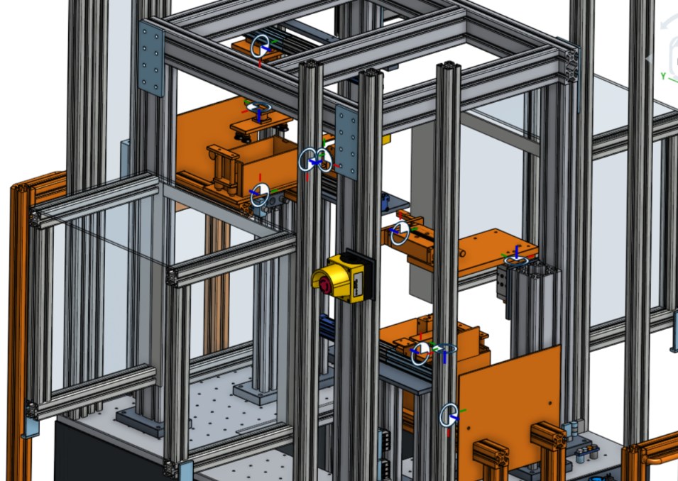
Implementing a line involves many people with different skills: designers, assemblers, electricians, programmers, operators, project managers and management. Each of these groups usually works from its own document, and a common picture of the final result only appears on the shop floor.
Stage 3 is meant to prevent that. The model from stages 1 and 2 is handed over as a working tool, available to everyone taking part in the implementation.
Why our own software
Typical simulation tools are made for specialists. They require specialist knowledge and training, so only a few people work with the model, and the others see a video or screenshots at most.
That is why we created our own software. Its purpose is to make the model more accessible and to make the work easier for everyone involved in the implementation. It runs on a computer and does not require learning a new engineering environment.
What the team receives
- The working process model, the same one on which the output was verified and the programs were tested.
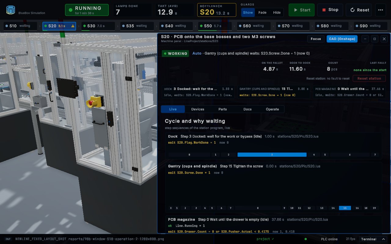
- Live line status: the state of each station, the current sequence steps and the conditions each sequence is waiting for.
- A window for each station: devices, parts and related documents, with the selected element highlighted in the 3D view.
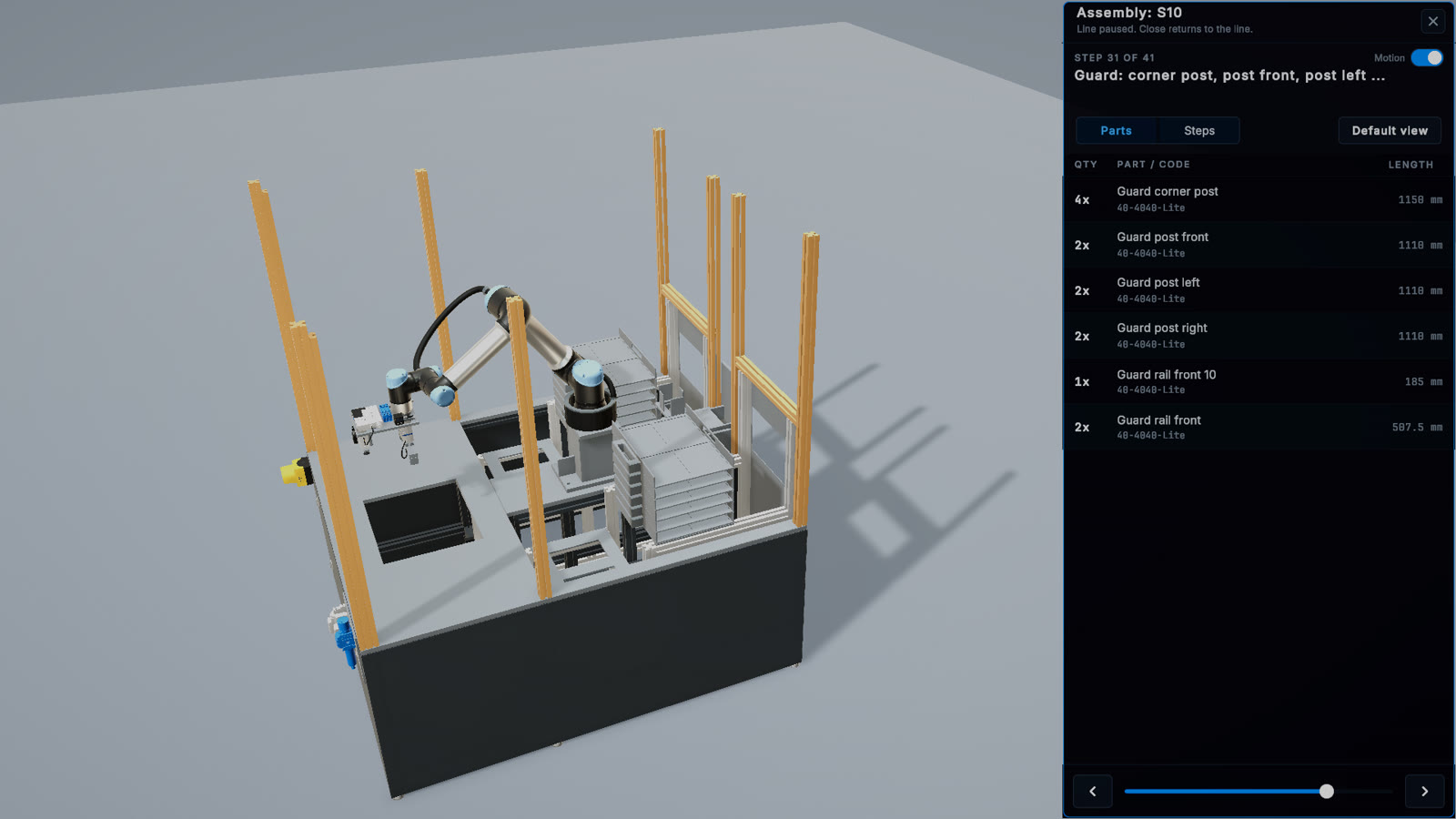
- Assembly instructions: step by step in the same software, for a station and the whole line.
- Signals: the list of inputs and outputs with their current values.
- Key figures: piece count, cycle times and the station that limits output.
Who uses it, and how
| Role | Use |
|---|---|
| Investor, management | Reviewing the target process and its output without reading technical documentation |
| Project manager | A common reference in discussions with contractors |
| Assemblers | Step-by-step assembly instructions, parts with quantities and codes |
| Electricians | Linking a signal to a device and its location |
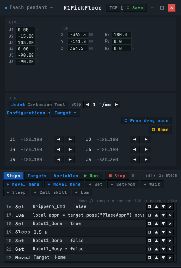
| Programmers | Seeing sequences and signals at work, testing program changes |
| Operators | Learning the line and its behavior on faults before commissioning |
| Maintenance | The location of components and their function in the process |
A reference for contractors
The greatest value of this stage is organizational. A drawing can be interpreted in different ways, while a working model shows the expected behavior unambiguously. When a question comes up about how a station should work, or in what order it should carry out its operations, the answer can be checked in the model instead of being settled in a meeting. The same model then serves as a reference during acceptance.
How it is handed over
The model is delivered as a program installed on a computer, or as a link. The framework and the source project of the simulation remain with BlueBoxSimulation, and further changes to the model are carried out as a separate order.
What this stage does not cover
The model is not compliance documentation or a machine operating manual, and it does not replace training on the physical line. It shows the intended result and the behavior of the control system, not the state of the real installation. A connection to a running line is not part of this stage.
The next step
With the model, the lists and the instructions, the team can move on to building. If the plant has no contractor of its own, our partners carry out the assembly under a contract with us, and we supervise that the work matches the design.